The overall problem:
For advanced lighting in somewhat traditional renderers (without ray bouncing) we still need to sample various volumetric / area lights. The prevailing method, MRP (Most Representative Point) volume sampling, suffers from glaring artifact edge cases that over the years nobody fixed.
I’ll focus here specifically on the case of tube lights / line lights, because I recently needed them in a strict no-compromise scenario. But the same issues exist on e.g. Quad Lights (especially if you expect to make them 3D volumetric).
(You can also see the results in my open source openxr framework.)
Here’s a TL;DR video:
No I mean it, all the fancy papers, engines, shadertoys, rockstar authors (who for the record I believe to be smarter than me), have the same artifacts. Not throwing anyone under the bus but go to literally any pretty shadertoy or engine that features line or tube lights, and cycle the specular component, point the light at these odd angles against a wall and a sphere, change your view angles, and you see these deal-breaking problems.
The solution:
My shader is here and the function is MRPointOnTubeLight with plenty of comments, but let’s discuss high level, stream of consciousness. (todo: make cleaner shader for the article 🙃).
We need to handle all these things and their problems:
1. Horizon intersection
This is well documented. Handle the case where the light intersects with a horizon or surface (see frostbite paper). Basically if one (but not both) ends of the light are behind the surface normal, we find the closest point on the line that is the same side of the surface normal. The most optimized way is to subtract from that point a dot-projection-based distance.
This works but keep in mind any caps or distortions you might add to the line / shape.
2. 1st MRP for specular component
This is sold as the only thing you need for speculars. High level idea is straight-forward: spec = reflection. So find the closest point on the line in its reflection on the fragment.
See Frostbyte’s paper (search for MRP), or Alex Tardif, or Redorav, or Unreal / Brian Karis, or Unity.
And Linear-Light Shading with
Linearly Transformed Cosines (Eric Heitz and Stephen Hill) which has excellent visualizations.
Some of these sources, e.g. Karis, Frostbyte, Unity, mention they know of (some of) the artifacts and simply accept them.
Problem
The concept of this math doesn’t work when the direction of the fragment to the light segment is approaching dead-on the same as the direction of the reflection vector. And, the tspec term causes a hard cutoff at the ends of the line/segment. This is not uncommon; as you saw in the videos, the distribution is wide and you notice the problems even at >45 degree angles:
- There’s a “cylindrical edge” hard falloff artifact in the reflection on the side of the line light that’s furthest away from the fragment point (which should be the blurriest side not the sharpest).
- And you get an “empty center hole” that you need to cap (duh there’s no line to pick a point on anymore).
3. 2nd MRP for diffuse component
Same idea, but the point is defined by the middle: the bisector of (frag->l0, frag->l1) touching l0->l1. Nicely visualized in Redorav’s article, or Linear-Light Shading with Linearly Transformed Cosines (Eric Heitz and Stephen Hill).
Problem
Practically the same issue. Can’t work when the direction of the fragment to l0 and/or l1 approaches the direction of the reflection vector. So you get big holes along the distribution of fragments. And because the diffuse is, well, diffuse, large, you also see it break towards the curve-horizon when you hold your light “parallel” to a sphere.
4. The caps
So if you want a volumetric light, you need to add (volume and) caps, and this would hopefully fix the 2nd “empty center hole” problem. Right?
Check page 18 “Adding the End Caps” in Linear-Light Shading with Linearly Transformed Cosines (Eric Heitz and Stephen Hill) but then also page 21 “The caps approximation is not always worth it and can result in visually disturbing artifacts.”
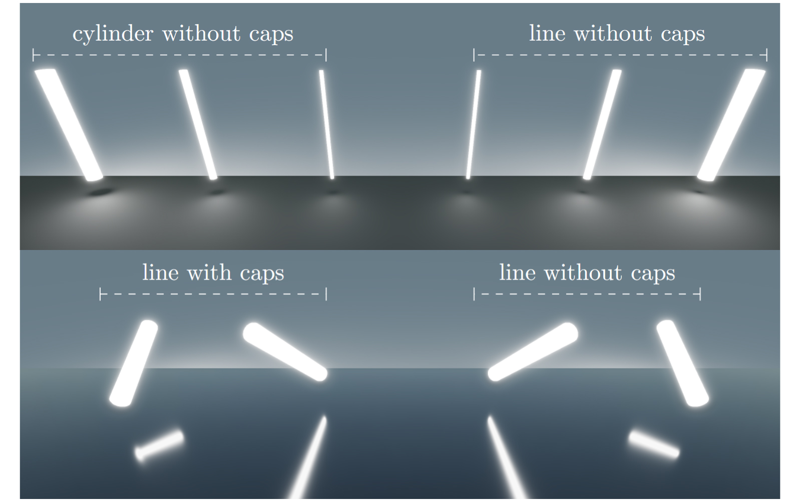
I see those artifacts and raise you another artifact, which happens even without the caps! In the video on the left half:
The horizon skew problem: when the reflected line is ~parallel to the surface (e.g. ground), and the light is big / long / far away, the reflection’s end of the line that’s closest to you, appears to have a downward sharp slope at the very end. And the end furthest from you gets an upward slope distortion.
Yes everyone seems to also have this problem. Unless they cap the cylinder or pinch it somehow.

So we have:
- a “cylindrical edge” hard falloff artifact
- an “empty center hole” that you need to cap
- a horizon sphere falloff problem
- a capping problem
- a horizon edge skew that happens without the cap
5. A 3rd MRP and patches
My magical but annoying fixes:
-
Specular term: We shorten the ends of the tube distribution exponentially in a tight and roughness-aware way (glorified pows and lerps towards the ends of the line). After some effort it nicely rounds the ends, but shortens the caboose/furthest end of the tube reflection a tiny amount. Hey it’s not more inaccurate than the aberrating original.
-
Everything: We pick a 3rd MRP that’s a simple point / sphere light position equivalent. And we try to include it where the other MRPs fail e.g. at the closest point on the tube to the surface. But, now we’re blending between one MRP and another MRP, based on angles, whereas IRL you get “infinite MRPs”. So because we got MRP1 <-> MRP3 for diffuse, MRP2 <-> MRP3 for specular, it won’t blend perfectly out of the box. But it’s close! I only needed to go into lerp hell to make sure I cat-heard all the math consistently across different smoothness / roughness and size and distance.
-
For better caps / ends: You can fade the intensity of the tube light towards its ends in some exponential curve way so it muffles the ends only, then substitute with the point or sphere light. We even have enough math already to tell which end of the light (reflection) is closest to us. For tentacles I just faded to 0 by some pleasing curve, without caps.
Drawbacks:
- “It’s not accurate”. Oh, you mean the non-energy-conserving, artifact-ridden dealbreaker industry-standard MRP solution, is now not accurate despite now looking more or less flawless? (well I agree, it’s not accurate)
- It’s a little heavier, innit? Hell the cool kids just use the one specular MRP and hand pick values & poses, and pretend they got good lights. So fake it as much as you can I guess.
6. Add radius, distort the n dot l, and aPrime roughness/radius.
Well documented already, check shader and references. Keep in mind any caps or distortions you might add to the line / shape.
Then plug the light direction, distance, aPrime, nDotL, into your brdf function, and attenuate.
Conclusion:
I can even warp / animate / wiggle it a little bit before it starts breaking at the seams (ie the tentacles), so I’ve managed to make a reasonably™️ flawless™️ and accurate™️ volume light, across all roughnesses. Especially for XR / VR you can’t get away with less. And as a nice bonus, the whole thing plugs into whatever BRDF functions you already have / want to use.
So the (patched) MRP technique, has its uses. But by this point I’d rather do more proper raytracing into some sparse scene light data. Because it got too high maintenance and heavy compared to what you thought you’d be doing when you heard about the easy MRP geometric shortcuts. Not a fan of solutions that rely on black holes of tweaking or too much smoke.
PS: The scene runs on a RTX 4070 mobile at 90FPS (the refresh rate of the headset) with 8 (animated) tube lights and 2 directional lights, and a lot of transparent objects overdraw. It also runs on a RTX 2060 mobile with a bit of lag spikes if you have too much overdraw right on your face.